
How to Install a GFCI Outlet
Safely replace a standard electrical receptacle with a GFCI outlet by identifying line versus load wires, securing connections, and testing circuit protection.
Turn off the breaker, verify zero voltage, identify LINE and LOAD conductors, connect the GFCI exactly as its diagram shows, mount it, restore power, then press TEST and RESET. Stop and hire a licensed electrician if anything is unclear.
Watch: How to Install a GFCI Outlet Safely
Kill the circuit, identify line versus load, wire the terminals, and test the trip. · 3:47 minute walkthrough. The full written steps are below.
Electrical work has a hard stop point
A GFCI can prevent serious shock, but only when the LINE and LOAD wiring and grounding are correct. If the wiring is unclear, stop and hire a licensed electrician.
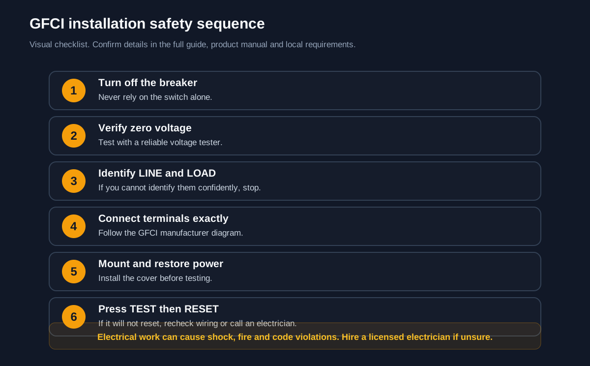
Before you start
- Turn off the breaker and verify zero voltage.
- Identify LINE and LOAD before disconnecting anything.
- Follow the GFCI wiring diagram exactly.
- Test and reset the device after restoring power.
Common failure points
- Never work on a live circuit.
- Do not guess LINE versus LOAD.
- Multiple cables can indicate a multiwire circuit or other complication.
Watch the original demonstration
See the source video before you start, then use the step checkpoints below as your field guide.
Play source video on YouTubeKeep learning
- Install a New Circuit BreakerRelated but higher-risk electrical work.
- Install a Ductless Mini-SplitAnother electrical home-improvement project.
- Install a Drop CeilingA safer DIY ceiling project.
Visual step map
See the full sequence before you start, then check off each step as you go.
0 of 7 steps checked
Materials and cost planner
Select the items you plan to buy, adjust any estimated price, and calculate the selected total.
Editable rough U.S. retail estimates. Estimated all listed: $133.00. Prices are planning estimates, not quotes — tax, store, brand, size and quantity will change them.
Time and finish planner
Estimate active working time from the number of steps in this guide.
Paint coverage calculator
Estimate how much paint to buy from the area you plan to cover, the number of coats and the coverage shown on the can.
Use the coverage printed on the actual product label. Rough, porous or heavily patched surfaces can use much more paint.
- Read the tools, materials, safety notes, and steps below for free.
- Tap See 20-second demo if you want to understand it first.
- Tap Start Camera Coach when you want hands-free help, or Voice-only if you do not want to use the camera.
- Allow camera and microphone. Point your phone at the work; the coach watches your progress and tells you the next step.
🧰 Required Tools & Equipment
- ✓ Non-contact voltage tester
- ✓ Wire stripper and cutter
- ✓ Phillips head screwdriver
- ✓ Flathead screwdriver
- ✓ Needle-nose pliers
📦 Materials & Supplies
- ✓ 15A or 20A GFCI outlet
- ✓ GFCI faceplate and mounting screws
- ✓ Wire connectors (wire nuts)
⚠️ Safety Checkpoints & Warnings
- • Shut off the correct circuit breaker and test both top and bottom sockets with a non-contact voltage tester before touching any wires.
- • Never connect incoming power wires to the LOAD terminals; incoming power must always connect to the LINE terminals.
- • Do not remove the yellow warning tape over the LOAD terminals unless you are specifically protecting downstream outlets.
📋 Step-by-Step Guide (7 Steps)
Turn Off Power and Verify Circuit Is Dead
Switch off the circuit breaker controlling the outlet. Insert a non-contact voltage tester tip into both receptacle slots and touch the faceplate screws. The tester must remain silent with no red light indicator.
- • Voltage tester tip placed directly into outlet slot showing solid green or no indicator light
- • Breaker handle firmly in the OFF position at the main electrical panel
- • Testing only one socket on a split-wired duplex receptacle
- • Trusting panel labels without physical verification
Remove Old Outlet and Expose Wires
Unscrew the wall plate and the two mounting screws holding the old receptacle in the junction box. Gently pull the receptacle forward by its metal yoke until the wires are fully extended outside the electrical box. Test each exposed wire conductor again with the voltage tester.
- • Old outlet hanging freely 2 to 3 inches away from the wall box
- • All attached black, white, and bare copper wires clearly visible and separated
- • Yanking wires forcefully, breaking brittle insulation
- • Failing to re-test bare conductors once exposed
Identify LINE and LOAD Wires
Disconnect the wires from the old outlet, keeping them separated and insulated from touching each other or the box. Turn the breaker back on briefly and touch each black wire with the voltage detector to identify the hot LINE wire supplying incoming power. Turn the breaker back off and verify power is dead again before proceeding.
- • The single live feed wire clearly marked with a piece of tape as 'LINE'
- • Breaker switched back off and confirmed dead with the voltage tester
- • Assuming top screws on old outlet correspond to LINE on the new GFCI
- • Leaving the circuit energized while handling wires
Strip and Prep Wire Ends
Trim any damaged wire ends with wire cutters. Use the wire stripper strip gauge to remove approximately 1/2 to 5/8 inch of insulation from each conductor. Straighten the wire ends cleanly using needle-nose pliers for insertion into the back-wire clamp terminals.
- • Exactly 1/2 to 5/8 inch of clean, nick-free bare copper exposed on each wire
- • Straight wire ends with no bends, twists, or fraying
- • Nicking the solid copper core with incorrect stripper gauge notches
- • Stripping too much insulation, leaving exposed hot copper outside the terminal body
Connect Ground and LINE Terminals
Attach the bare copper or green ground wire to the green grounding screw at the bottom of the GFCI. Insert the white neutral LINE wire into the back-wire clamp labeled 'LINE WHITE' (silver screw side) and tighten firmly. Insert the black hot LINE wire into the clamp labeled 'LINE HOT' (brass screw side) and torque screw down securely.
- • Black wire firmly seated behind LINE brass screw with no bare copper showing beyond the housing edge
- • White wire firmly seated behind LINE silver screw
- • Ground wire firmly fastened around the green hex screw
- • Connecting LINE wires to LOAD terminals hidden under the yellow tape
- • Reversing hot (black) and neutral (white) connections
Fold Wires and Mount Outlet into Box
Fold the electrical wires like an accordion back into the electrical junction box, keeping the bare ground wire away from the side terminal screws. Push the GFCI receptacle flush against the box and drive the top and bottom mounting screws straight into the box ears. Snap or screw on the finished wall plate.
- • GFCI receptacle sits perfectly vertical and flush against the drywall plane
- • Wall plate mounted square with no visible gaps or cracking
- • Forcing the outlet back aggressively and pinching wires behind the metal yoke
- • Allowing the bare copper ground wire to contact hot or neutral terminal screws
Restore Power and Test GFCI Function
Turn the circuit breaker back ON at the panel. Look for the status LED on the GFCI face (often solid green). Firmly press the 'RESET' button until it clicks, plug in a test lamp or circuit tester, then press the 'TEST' button to verify that power cuts out instantly before resetting it for normal use.
- • GFCI status LED illuminates green
- • Pressing TEST button creates an audible snap and cuts power to the connected tester
- • Pressing RESET restores power immediately
- • Leaving the GFCI in a tripped state without pressing RESET after restoring breaker power
- • Ignoring a solid or blinking red status indicator LED
Credit: inspired by an original tutorial by MrFixItDIY — watch the original on YouTube.
Don’t have everything?
- No Non-contact voltage tester? Plug-in GFCI receptacle tester with digital voltage readout
- No Wire stripper? Lineman's pliers with integrated wire cutting and stripping notches
Frequently asked questions
What is the difference between LINE and LOAD on a GFCI?
LINE is the incoming power source. LOAD feeds downstream receptacles that the GFCI will protect. Reversing them can prevent the device from working or protecting correctly.
Can I install a GFCI outlet myself?
Only if you are confident, can verify power is off and can identify the wires correctly. Otherwise hire a licensed electrician. Electrical mistakes can cause shock, fire and code violations.
Why will the GFCI not reset?
A GFCI that will not reset may be miswired, defective or protecting a circuit with a fault. Turn off power and recheck the wiring or call an electrician.
Where are GFCI outlets required?
Requirements vary by location and code, but GFCIs are commonly required in kitchens, bathrooms, garages, outdoors and other wet areas. Check the current local rules.